10:1 Ultra Wide Input Range DC/DC Converters for Railway Applications

The New range of HAE150U and HAE200U DC/DC Power Converters are suitable for the harsh mechanical and electrical environment of traction vehicles and rolling stock applications. It has an ultra-wide input voltage range from 16V to 160V and covers all the input power systems of railway applications which are 24V, 28V, 36V, 48V, 72V, 96V, 110VDC. Ultra-wide input voltage converters usage has risen lately, due to the increase of onboard electronic systems such as video surveillance, access and ticketing machines, passenger device-charging USB ports, infotainment, information systems and telemetry. According to EN50155 standard (defines the supply requirements for electronic equipment in rail applications), equipment powered directly from batteries with no voltage stabilizing device must function properly with input voltages that range from 0.7VN to 1.25VN during normal operation. The equipment must also withstand input voltage drops of 0.6(VN) for 100 ms and overvoltage surges of 1.4VN for one second that may occur during startup. The HAE150U & HAE200U Series with its input voltage range from 16V -160V or 12VDC in transient operation meets stringent railway sector performance standards. Up to 93% high efficiency means a reduced requirement for cooling, and their remote on/off facility enables simple, reduced power consumption in the off condition. Plus, it reduces the capacitance of hold-up capacitors by applying the enhanced hold-up function to meet the requirements of supply interruption and change-over. HAE150U and HAE200U feature full protections, such as: over current protection, short circuit protection, output over-voltage protection, input under-voltage lockout, over-temperature protection, etc. HAE150U and HAE200U meet IEC 62368-1, EN 50155, and EN 45545-2 for ITE and railway applications. HAE150U Railway Standards Ultra Wide Input DC/DC Converter: 150W Read more HAE200U Railway Standards Ultra Wide Input DC/DC Converter: 200W Read more DC-DC Converters EN 50155 Approved – Related Products For technical support about our off the shelf products and customised power conversion solutions, get in touch today. Contact Our Engineering Team
COVID-19 Message From Our CEO

Dear Customer & Partner, The recent events regarding the Covid-19 virus have thrown the world into turmoil. At Helios we are proud to say it is pretty much business as usual, our sales, manufacturing and service departments are running at normal capacity, and our supply lines for products are secure, albeit with some delays on some items. The rapid decline in value of the AU dollar, however, is out of our control, and there will need to be price adjustments on some items not currently in stock as time progresses. We will do our utmost to minimise cost increases, and to honour existing quotes. We take the health impacts of this virus very seriously and have implemented a number of measures to ensure our staff and visitors are as protected as possible. These include: Upgraded cleaning of work surfaces and points of contact Strong emphasis on personal hygiene by staff Strong emphasis on social distancing between staff, and staff and visitors We welcome you to maintain contact with our business and people but suggest you only visit if you really need to Any staff that are unwell or have been overseas in the last 14 days are self-isolating. Most of our sales and admin functions can now be carried out remotely, and key staff can work from home if required to self-isolate, or if unwell. Our Sales Engineers are available and working at the office right now, please do not hesitate to contact us on sales@heliosps.com.au We are committed to maintaining our ability to provide our world-leading power solutions to our customers and look forward to meeting your needs in these difficult times. Regards Greg Russell CEO
DC Power Supplies for DC Motors
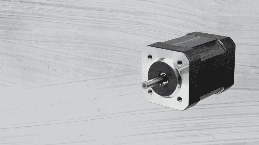
How to select the right DC Power Supply for DC Motors? Motors, solenoids and relay controls require higher levels of current during start-up than they do for continuous operation. Mechanical failures such as motor stalls or due friction can increase the current draw dramatically. When designing or installing a DC motor supply, many factors such as back up, loading, speed variation, regenerative current and others should be considered. At Helios, we recommend that when selecting a power supply for your DC Motor, you should be aware of at least the following aspects: Maximum Current required: High currents drawn above the motor rating can cause motor seizures, overloads and motor failures causing heating and not rotating. Constant Current limit: Not one that goes into hiccup mode this means that, should an overload occur, the output current stays at its limit point, and the output voltage reduces towards zero. Typically, the supply will automatically return to its normal output voltage when the overload condition is no longer present.ie when the motor is running normally. Output diode required: To prevent the power supply being damaged by reverse voltage spikes which occur when the supply is turned off and the motor is slowing down. To illustrate, here are examples for brushed dc motor and a brushless dc motor Brushed DC motors With this type of motor, the magnets are stationary and the coil rotates. Electricity is transferred to the rotating coil by the use of “brushes”. The advantages of this type of motor are low initial cost and easy speed control. When the power is interrupted, the motor coil will act like an inductor and will try to continue to produce current, effectively becoming an inverted voltage source. This will apply a reverse polarity to the power supply and can cause damage to the motor. (Back EMF – Electro-Magnetic Flux) By using a diode, as shown below, the diode provides a current path for the reverse motor current and will clamp the reverse voltage to a level no greater than the forward voltage drop of the diode. This protects the power supply’s output capacitors and other components from being stressed by the reverse voltage. Brushless DC motors Brushless DC motors, often referred to as BDCMs or BLDC motors, have permanent magnets that rotate and a fixed armature Although this option can be more expensive, providing higher reliability in the long term having no brushes or commutator wear plus enabling position control to be more accurate. When the motor is turned off or reversed, it will act as a generator and produce a high voltage spike. This spike can cause the power supply’s overvoltage protection to trip, shutting down the unit. By using a diode in series with the output, as shown below, the spike will be blocked from interfering with the power supply. [1] [1] Posted by Power Guy http://power-topics.blogspot.com/ Variable Speed – DC Motors Changing the voltage applied to the armature of the motor is one of the ways to better control DC Motor’s speed. We suggest for a specific application to use a power supply with a programable output voltage. As every application is different and there are many factors to be considered that can or may affect the final design. Contact Our Team of engineers if you require more information about how to power and backup your DC Motor.If you require more information about how to power and backup your DC motor please use our contact page or call +61 2 7200 9200 DC Power Supplies for DC Motors HDS1500 Programmable AC-DC Power Supply: 1500W $1,852.00 Select options HDS800 Programmable AC/DC Power Supplies: 800W $730.00 – $965.00 Select options SWS600L – SWS1000L – AC/DC Single Output: 600W – 1000W Read more Sold out HDS3000 – AC/DC Programmable Power Supply : 3000W $3,613.00 Select options Sold out SR 100HL – AC/DC Power Supply 100W with Comms Read more Sold out SR 250HL – AC/DC Power Supply 250W with Comms Read more Diodes & Redundancy Modules DRM40 DIN Rail Mount Redundancy Module 20A & 40A $139.00 Select options P Series Output Diode For Parallel & Redundancy Applications up to 400V Read more
New Modular OPUS HE Battery Charger Systems for Industrial Applications
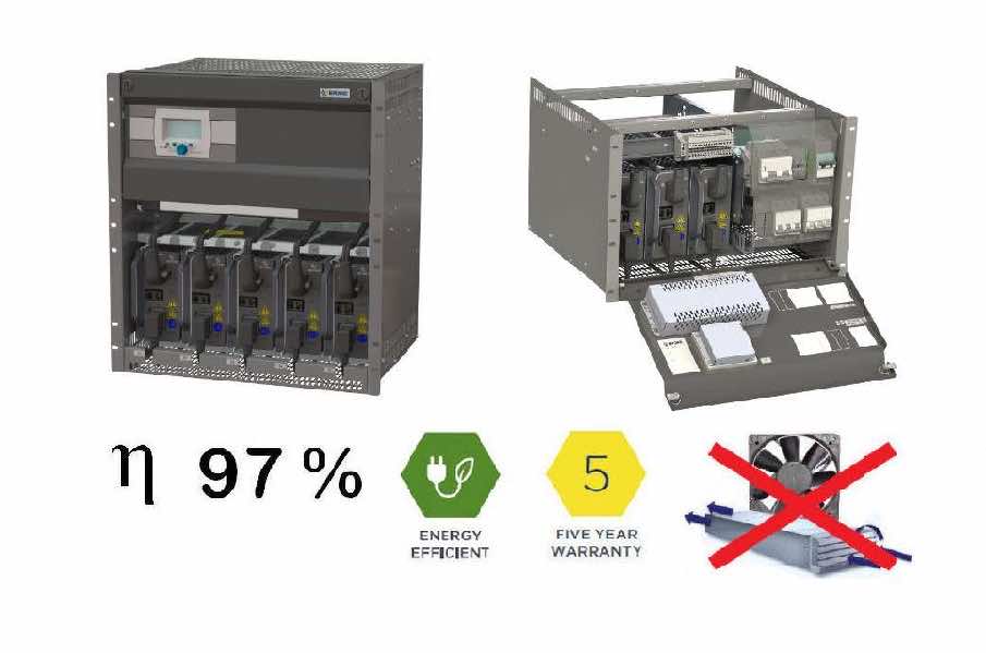
The new Efore OPUS HE family of 19” rack-mount DC power systems are high-efficiency power solutions powered by the new MHE 2kW high-efficiency rectifiers. The 7U rack configuration delivers up to 6 kW of power, while the 12U configuration delivers up to 10 kW. Their robust and reliable fan-free design, modular architecture and use of established components – including the VIDI+ controller and flexible distribution options – ensures the lowest total cost of ownership (TCO) across the 15-20 year expected life span for industrial backup power systems. The OPUS HE series products offer unrivalled efficiency of 97% for minimal environmental impact. They have been designed and optimized for critical infrastructure, distribution and transmission substations, process industries, and railway substations where reliability is always the top priority. New MHE Rectifiers – 5 Warranty MHE rectifiers are convection cooled and require no fans. Rated output power is 2000 W in 48 V – 220 V output versions and 1500 W in 24 V version. Rectifier input is single phase, range 85-300 VAC. 2000 W output power, 24 VDC 1500 W Soft-start generator input feature Active load current sharing Internal over temperature protection Digital communication over CAN bus with Efore VIDI controller Modular Battery Chargers – DC UPS with MHE Rectifiers The MHE rectifier is designed to supply power to industrial and telecom backup power systems. It should only be assembled and used in a system cabinet or sub-rack where human contact with hazardous voltages is prevented.19” 12U Rack delivers maximum 10 kW output power at 48, 60, 110, 125 and 220 VDC and 7.5 kW at 24 VDC output and 19” 7U Rack delivers maximum 6 kW output power at 48, 60, 110, 125 and 220 VDC and 4.5 kW at 24 VDC output. These rack systems support all typical Lead Acid and Ni-Cad battery systems in nominal 24, 48, 60, 110, 125 and 220 voltages. Opus HE 7U Modular Battery Chargers DC UPS Opus HE 12U Modular Battery Chargers DC UPS Proven Quality & Reliability More than ten years providing OPUS DC systems to the industrial sector in New Zealand, Australia and Asia have reassured the high level of reliability and quality of Opus DC Systems. Power Utilities, Refineries, Mining and Critical Infrastructure ( Hospitals & Transport Centres) have been few of the applications where our Turnkey Solutions are installed. Check out the case study below; we had the opportunity to supply six redundant, modular & fanless battery charger systems to the power grid company in Bangladesh. For this specific project, we integrated the first version of Opus MRC Rectifiers and 7U Rack Mount System (still available) which have the same level of reliability but less power density. Case Study Modular & Redundant Battery Chargers for Six Electrical Substations In Bangladesh Contact Our DC Systems Expert Features of CAB 716 48VDC Dual 3.2kW battery charger in a 45U 600mm W x 600mm D cabinet Two 230VAC Mains Input Connections Float Voltage of 56.8VDC configured for NiCd batteries Single DC Distribution with 10 x 10A 2P load breakers with Auxiliary switches Configured for redundancy by two +P95 blocking diodes Two 100A 2P Battery MCB’s, one for each battery Temperature sensor with temperature compensation A Low Voltage Disconnect set at 40VDC for each charger End customer: Power grid company in Bangladesh MODBUS SNMP Products Installed in CAB 716 OPUS HE DC Power Systems MHE Rectifiers 2000W Read more OPUS HE 7U Modular Battery Charger Up To 6kW Read more SR Series Meter – DC Volt/Amp Meter Read more VIDI+ System Controllers Read more
IHP Configurable High Power System – Rack Mount Inverters
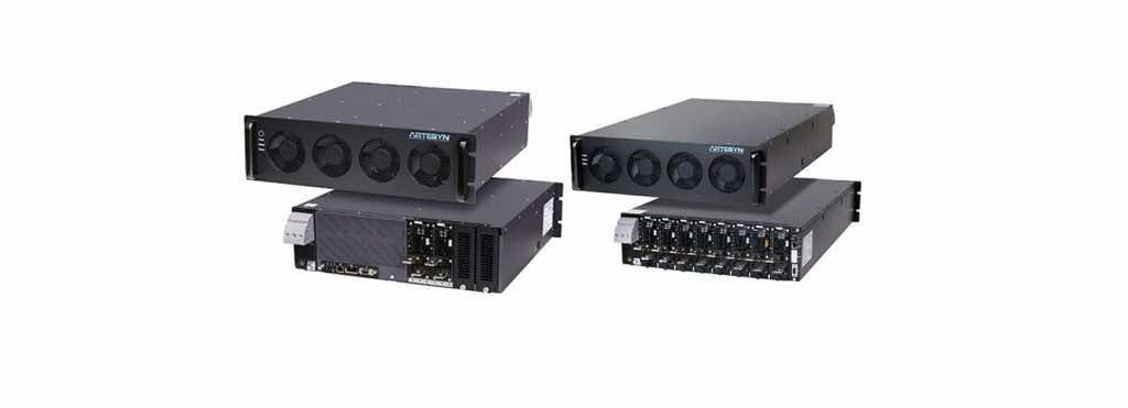
IHP Modular Configurable Intelligent High Power System-Up To 24000 Watts https://www.youtube.com/embed/E0xL2ZwP6x8 Total Power: Up to 24 KW Input Voltage: 180-264 Vac 342-528 Vac Single Phase or 3-Phase # of Outputs: Up to 8 Our engineers will size and configure the right solution to meet your applications’ needs by using a wide variety of plug-in modules that address a large range of voltages and currents. Every project is different and has the same importance for us. Don’t hesitate to get in touch; Helios DC experts will take great care to understand the real needs and objectives of your power system. 19″ Rack Mount Inverters with optional SNMP interface – Digital Display– Alarm Relay Contacts– Inverter mode or UPS mode by switch ( UIP models)– Protection: Input Undervoltage, Input Overvoltage ,Overload Short circuit , Low battery alarm ,Over temperature RM – PSW Series of Inverters offer a wide range of customizable features to meet the stringent specifications of your application Series Power (kVA) PF Input Voltage (VDC) Output Voltage (VAC) RM-PSW1KVA1U 1 0.85 12 V 100/110/115/120V(Switch Selectable) RMS±3% 24 V 200/220/230/240V(Switch Selectable) RMS±3% 48 V RM-PSW2KVA1U 2 0.85 12 V 100/110/115/120V(Switch Selectable) RMS±3% 24 V 200/220/230/240V(Switch Selectable) RMS±3% 48 V RM-PSW3KVA1U 3 0.85 24 V 100/110/115/120V(Switch Selectable) RMS±3% 48 V 200/220/230/240V(Switch Selectable) RMS±3% RM-UIPSW2KVA2U 2 1 12 V 100 ~ 120V (Tune VR) 24 V 200~240VAC (Tune VR) 48 V 110 V 220 V RM-UIPSW3KVA2U 3 1 12 V 100 ~ 120V (Tune VR) 24 V 200~240VAC (Tune VR) 48 V 110 V 220 V RM-UIPSW5KVA3U 5 1 12 V 100 ~ 120V (Tune VR) 24 V 200~240VAC (Tune VR) 48 V 110 V 220 V Customizable Options:1. DC Input Range 2. Conversion time By-pass 3. Alarm Relay Contacts 4. SNMP interface 5. Digital Display FAQQ Please explain power loss of power supplies.A The power loss of power supplies is the difference between input active power and output power and is calculated with the formulas below.Power loss= input active power – output powerInput active power can be calculated with the output power ÷ efficiency, sopower loss= (output power ÷ efficiency) – output power.